
INSTALLATION DIAGRAM
Installation
Before proceeding with the installation of a vapo- rizer, please inquire and comply with local regulations for LPG equipment. Install the vaporizer on a level, firm base made of non-flammable material. Firmly anchor it with the four screws in a location with good ventilation, preferably where there is no vehicle traffic. The vaporization system must be done according to Figure No. 1, as described in Table No. 5, which details each models inlet and outlet pipe diameters.
The installation described in Figure No. 1 is for the basic system that in addition to complying with applicable national and international standards has proved to be the easiest and most efficient. Pipeline dimensions must be proportional to the flow rate that will be used. As well as, to the pressure drop calculated from the regulation block to the consumption centers, making sure the installation is projected with two-stage regulation.
Vaporizer Functionality
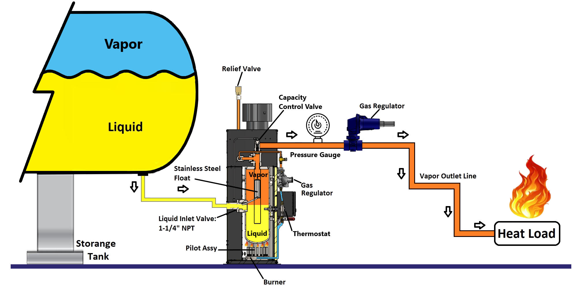
When opening the bypass valves, the liquid will flow either by gravity or by pressure difference from the storage tank to the vaporizer heat exchange containers. The flow will stop when the liquid level raises the floater inside that will automatically close the inlet valve.
When the burner is turned on, the heat it provides will accelerate the liquid’s evaporation inside the heat exchanger, generating the sufficient amount of liquid to supply the system. As a consequence of this, the liquid level will decrease inside the exchanger, making the floater drop, opening the inlet valve to replace any evaporated liquid.
In constant demand conditions, the inlet valve will remain partially open, replacing the liquid as it evaporates.
In variable demand conditions, the inlet valve will open and close as the liquid level varies inside the exchanger. The incoming liquid will be heated and cooled according to demand, turning the thermostat on and off.
Whenever the vaporizer is in operation and the liquid inside the exchanger has reached the temperature at which the thermostat was calibrated, the main burner will turn off and the liquid level will drop, activating the inlet valve which will allow cold liquid back in. This will turn the thermostat on, igniting the main burner. This cycle will continually repeat itself as the vapor phase propane demand varies.
Requirements for installations in the USA and Canada.
Canadian Installations: The vaporizer and piping shall be installed in accordance with Natural Gas and Propane Installation Code, CAN/CSA-B149.1, the Canadian Propane Storage and Handling Code, CAN/CSA-B149.2, and electrical components installed in accordance with the Canadian Electrical Code, CSA C22.1, Part I.
US Installations: The vaporizer shall be installed in accordance with Liquefied Petroleum Gas Code, NFPA 58, and electrical components installed in accordance with the National Electrical code, NFPA 70.